Simple electronic device could revolutionize the solar and electric car industry

Over 100 years ago Nikola Tesla informed the solar and electric car industry how to produce kWs of energy from just 10 watts.

“When it was charged full, I discharged it suddenly, through a short circuit which gave me a very rapid rate of oscillation. Let us suppose that I had stored in the condenser 10 watts. Then, for such a wave there is a flux of energy of (4 x 10⁴)2, and this is multiplied by the frequency of 100,000. You see, it may go into thousands or millions of horsepower.”

by discharging the condensers, either through a stationary gap or through a gap with a mechanical interrupter, I obtained any frequency I desired, and perfectly undamped waves.”

During a 1891 New York lecture Nikola Tesla started:

“The discharge of a condenser affords us a means of obtaining frequencies far higher than are obtainable mechanically.”

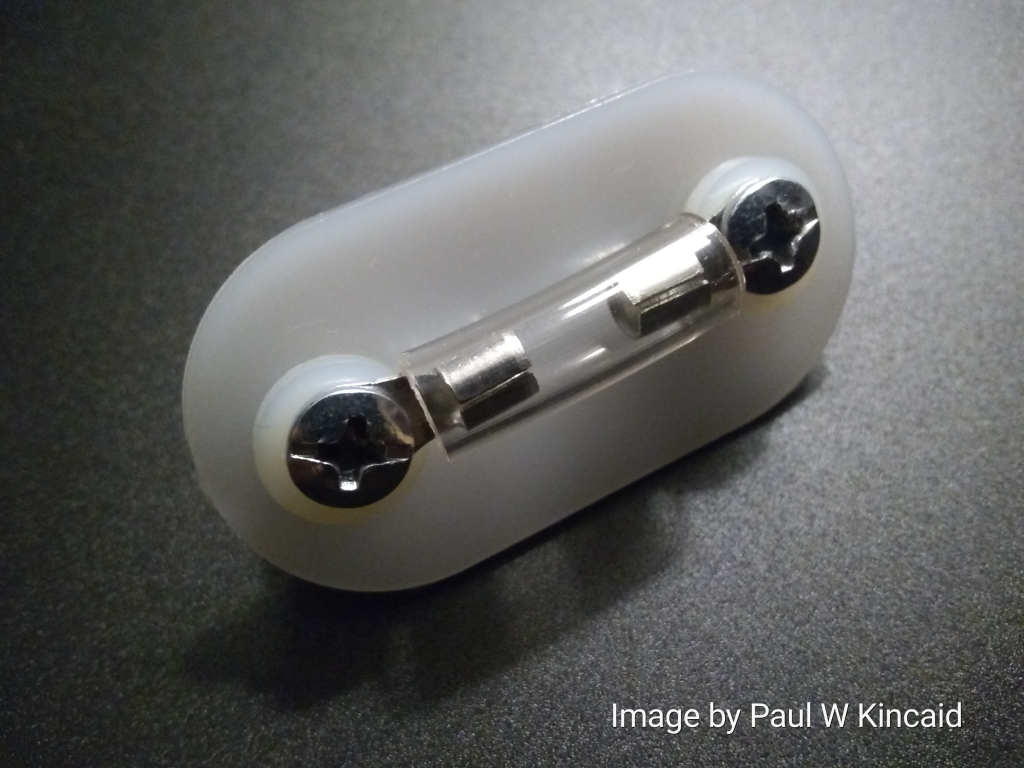
Spark gaps played a central role in many of Nikola Tesla’s high voltage devices. In its simplest form, a spark gap is nothing more than two electrodes with some space in between (see image above of a simple spark gap made by Paul W Kincaid) through which an electric spark passes when the voltage in a circuit reaches a high enough level.

“Whenever you say “the break”, you mean “a spark gap”?” lawyer asked Nikola Tesla in 1916

“Yes; otherwise I use the term “circuit controller, preferably”. Nikola Tesla

“With small currents through the gap it is best to employ aluminum, but not when the currents are large.” Nikola Tesla

Therefore, by connecting a 10 watt solar panel to a capacitor and thereafter discharging the capacitor suddenly, through a short circuit (a spark gap), a 10 watt solar panel’s output could potentially be transformed into kWs of energy.

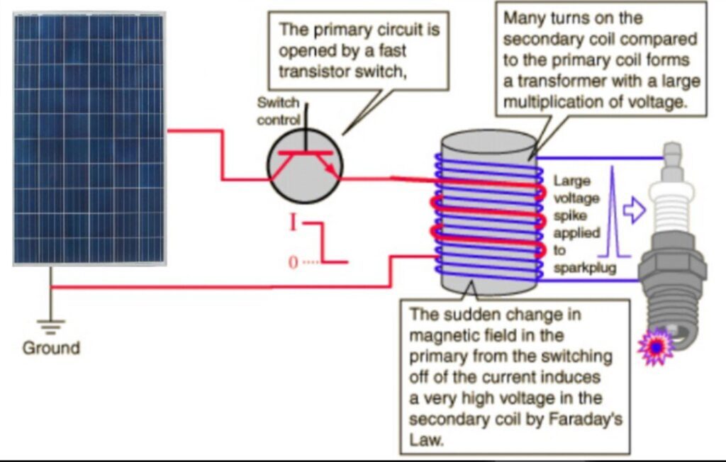
An automobile’s ignition coil does essentially the same thing. An ignition coil’s primary function is to transform the car battery’s 12 volts into the 30-40,000+ volts (30-40 kVs) needed to create an electric spark in the spark plugs to ignite the fuel.

We can use Nikola Tesla’s ingenuity again today to not only revolutionize the solar energy industry, but to revolutionize the electric car industry too.

By connecting a solar panel to a mass produced ignition coil circuit, the solar panel’s low voltage could be transformed into the thousands of volts (kVs) needed to power our homes, cottages and industries.

“The disruptive voltage when the spark is taken between points is approximately 30,000 volts per centimetre for spark lengths up to 2 or 3 centimetres, after this it is somewhat less, as the dielectric strength of air is relatively greater for small thicknesses.” 1914 publication – WIRELESS TELEGRAPHY, A HANDBOOK FOR THE USE OF OPERATORS AND STUDENTS, BY W. H. MARCHANT

Method for harnessing renewable energy from all directions

Solar antenna designed by Paul W Kincaid was designed to harness radiant energy from all directions. It was designed to take up less space than a solar panel. It was designed to harness more energy than a solar panel.

There are a number of flaws in the design of solar panels that makes them very inefficient in harnessing solar energy. The very thin strips of conducting material in solar panels can of course only harness very little energy. Replace the thin strips with thin metal sheets or discs and you increase the inductance of the solar panels. A thin sheet of conducting material has a much greater inductance than very thin strips.

The thickness or gauge, of a conducting material has an inversely proportional relationship to resistance. The thinner a wire is, the greater resistance it has; this is because thinner wire has fewer electrons to carry an electric current. Solar panels are essentially made of very thin conducting material which makes them unable to efficiently carry an electric current.

A thicker wire or a metal plate will have a greater area and therefore will have less resistance and will prove to be better conductors of electricity than a solar panel’s very thin conducting material which inherently have a higher resistance.

Electric current will flow more easily through a thick wire than through a thin wire when connected to the same source.

The solar antenna has multiple elements which work together as a single antenna to harness various forms of electromagnetic energy. The individual elements are connected to a single receiver feedline that feed the harnessed power to either rechargeable batteries, power packs or super capacitors.

The solar antenna is an omnidirectional antenna, a class of antenna which can harness various forms of electromagnetic energy from all directions. That’s an important feature because:

“Electric power is everywhere present, in unlimited qualities. This new power for the driving of the world’s machinery will be derived from the energy which operates in the universe, without the need for coal, gas, oil, or any other fuel”. Nikola Tesla

The solar panel design utilizes a method Nikola Tesla used in 1901 (over a 120 years ago) to harness radiant energy.

In Nikola Tesla’s energy harnessing patent Tesla used an antenna. Nikola Tesla also powered a steel frame electric motor converted Pierce Arrow automobile using an antenna. Tesla used an antenna to power an electric car that had just one 12 volt Willard battery. Nikola Tesla successfully demonstrated that more energy can be harnessed by an antenna than by any solar panel manufactured today.

In patent US685958A – Method of utilizing radiant energy you can clearly see that Nikola Tesla used an antenna that was made of a single sheet of highly polished and insulated metal plate to harness radiant energy:

“In applying my discovery I provide a condenser, preferably of considerable electrostatic capacity, and connect one of its terminals to an insulated metal plate or other conducting body exposed to the rays or streams of radiant matter. … an insulated conducting body connected to one of the terminals of a condenser, while the other terminal of the same is made by independent means to receive or to carry away electricity. A current flows into the condenser so long as the insulated body is’ exposed to the rays, and under the conditions hereinafter specied an indefinite accumulation of electrical energy in the condenser takes place. This energy after a suitable time interval, during which the rays are allowed to act, may manifest itself in a powerful discharge, which may be utilized for the operation or control of mechanical or elecitrical devices or rendered useful in many other ways. … The insulated plate or conducting body should present as large a surface as practicable to the rays or streams of matter, I having ascertained that the amount of energy conveyed to it per unit of time is under otherwise identical conditions proportionate to the area exposed, or nearly so. Furthermore, the surface should be clean and preferably highly polished or amalgamated”

Antennas are used by ionosphere heaters in the US, Russia, China and Germany reoccupied Europe to transmit enormous amounts of energy into the atmosphere to heat up the atmosphere and cause climate change/weather modification. Ionosphere heaters use antenna arrays to fabricate climate change in a targeted area.

An antenna array is a set of multiple connected antennas which work together as a single antenna, to transmit or receive radio waves. The individual antennas are usually connected to a single receiver or transmitter by feedlines that feed the power to the elements in a specific phase relationship.

Ionosphere heaters use antennas because an antenna can either transmit energy or receive energy or both. An antenna is a transducer. A transducer converts one form of energy to another.

An antenna is an electrical device which converts electric energy into radio waves, and vice versa.

During the receive mode of operation, an antenna converts electromagnetic (EM) energy into electrical energy. The solar antenna is designed to operate only in receive mode – convert the EM energy that is all around us into electrical energy.

Innovative renewable energy technology designed to produce renewable energy with zero CO2 emissions

More than two-thirds of the world’s energy is wasted as heat. Paul W Kincaid’s latest renewable energy technology design was designed to utilize thermal conduction to convert heat into renewable energy. The undeveloped technology (undeveloped due to lack of funding) utilizes the heat from asphalt roofs to produce renewable energy with zero CO2 emissions.

Thermal conduction is the transfer of heat energy from one substance (asphalt shingles) to another (metal sheets or foils) or within a substance. Conduction is a very effective method of heat transfer in metals.

Asphalt roofs are the logical choice for harnessing CO2 free renewable energy. Dark asphalt shingles absorb an enormous amount of solar radiation. Nearly 90% of solar energy that hits our rooftops is absorbed and is then converted to heat. During the day, your roof can reach very high temperatures. For example, a standard asphalt shingle can be as hot as 60 – 75 °C.

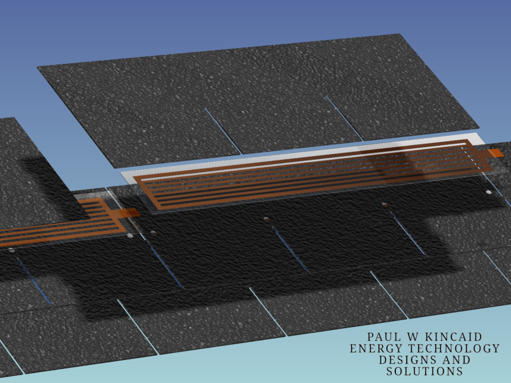
This renewable energy technology was designed to be installed quickly and easily. The insulated “thermal conduction panels” were designed to be installed on either an existing roof or a new roof.
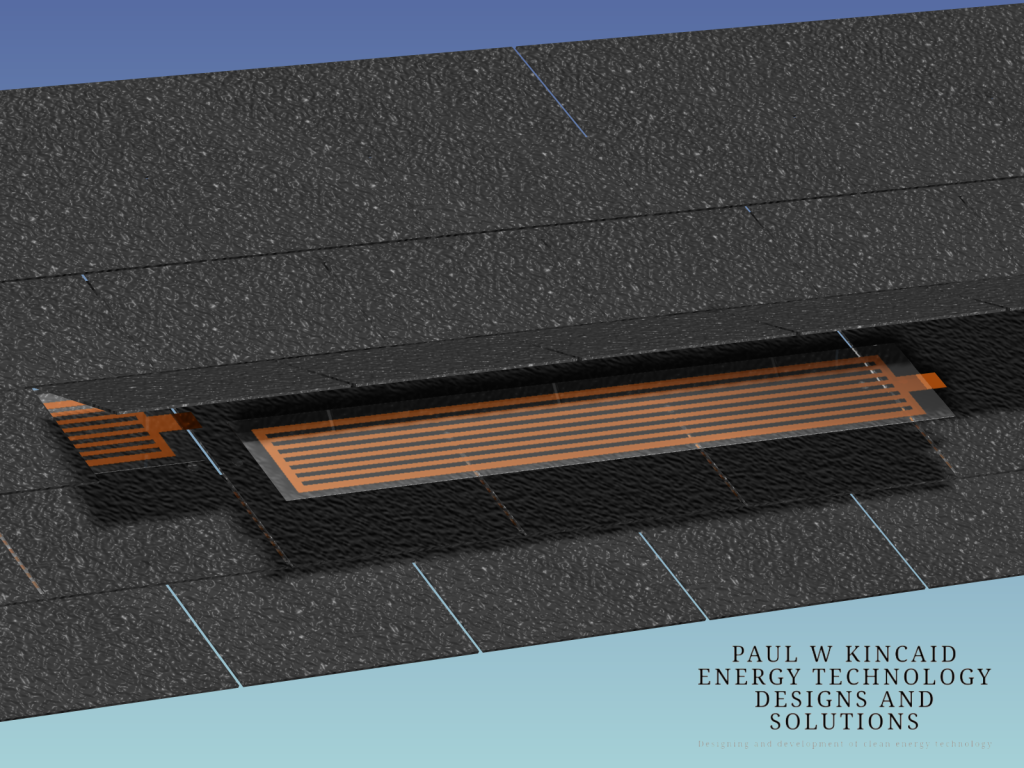
Need more energy? Install and connect more thermal conduction panels “in series” under your roof’s asphalt shingles.

This renewable energy technology design is based on a method Nikola Tesla used over 120 years ago to harness radiant energy. In the 1901 granted patent US685958A – Method of utilizing radiant energy Nikola Tesla harnessed radiant energy using a single sheet of highly polished and insulated metal plate.
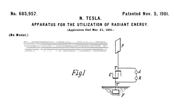
“The insulated plate or conducting-body should present as large a surface as practicable to the rays or streams of matter, I having ascertained that the amount of energy conveyed to it per unit of time is under otherwise identical conditions proportionate to the area exposed, or nearly so.” …

“My present application is based upon a discovery which I have made that when rays or radiations of the above kind are permitted to fall upon an insulated conducting body connected to one of the terminals of a condenser, while the other terminal of the same is made by independent means to receive or to carry away electricity, a current flows into the condenser so long as the insulated body is exposed to the rays, and under the conditions hereinafter specied an indefinite accumulation of electrical energy in the condenser takes place. This energy after a suitable time interval, during which the rays are allowed to act, may manifest itself in a powerful discharge, which may be utilized for the operation or control of mechanical or elecitrical devices or rendered useful in many other ways.” Nikola Tesla patent US685957A

Reading Nikola Tesla’s Patent US685957A we can clearly see from the information and images filed with the patent that Nikola Tesla used an insulated metal plate to harness energy – energy that is transferred by electromagnetic radiation, such as light, X-rays, gamma rays, and thermal radiation.

What “metal” did Nikola Tesla use in the patent for the insulated metal plate? Copper?

Copper has the highest conductivity of any non-precious metal and one that’s 65% higher than aluminum. Copper has the best electrical conductivity of any metal, except silver. Copper is a good conductor of heat (about 30 times better than stainless steel and 1.5 times better than aluminum). Most metals are pretty good conductors; however, apart from silver, copper is the best. Each copper atom has lost one electron and become a positive ion. So copper is a lattice of positive copper ions with free electrons moving between them. Electrons can move freely through the metal. For this reason, they are known as free electrons. They are also known as conduction electrons, because they help copper to be a good conductor of heat and electricity.

How much energy can be potentially produced by developing renewable energy technology that harnesses energy via thermal conduction?

“At high noon on a cloudless day, the surface of the Earth receives 1,000 watts of solar power per square meter (1 kW/m 2 ).” Caltech US Department of Energy, Office of Basic Energy Science , Washington, DC report under CONVERSION OF SUNLIGHT INTO ELECTRICITY p.15

“the Earth system—land surfaces, oceans, and atmosphere—absorbs an average of about 240 watts of solar power per square meter (one watt is one joule of energy every second)” NASA

Won’t know for sure until the thermal conduction panels are developed and installed on a roof and metered.

In the meantime, one asphalt shingle measures 12″ x 36″. Six thermal conduction panels installed under 6 shingles would therefore give you approximately 1 square meter of thermal conduction surface area. Six thermal panels are needed to make approximately 1 square meter because 1 thermal conduction panel is placed under half of a shingle.

That means 6 panels have the potential to harness from 240 to 1,000 watts of solar power.

Methodology

The flow of electrons is what creates electrical current. Electrical energy is energy produced by the movement of certain particles. This flow of particles is called electric current. Currents go in one direction at a time.

In order to energize a light bulb or turn on a computer, we need to produce a continuous electric current. To do this, we need an energy source. Common energy sources include the Sun, batteries and generators. An electric current also needs a path along which it can travel. An electric circuit is a pathway through which electric current flows.

Wires and the thermal conduction panel’s elements provide a path through which current can flow. Wires and elements are made from materials that carry, or conduct, electrons more easily than other materials. Materials that conduct electrons easily are called conductors. Copper and aluminum are good conductors. Wires are wrapped with a material called an insulator. This material does not easily carry electrons. Insulators keep the conductors inside a wire from touching each other and interrupting the flow of electrons. Rubber, plastic, and glass are good insulators. The spacing of the thermal conduction panel’s elements keep the conducting elements from touching each other and interrupting the flow of current.